This post contains affiliate links. Learn more here.
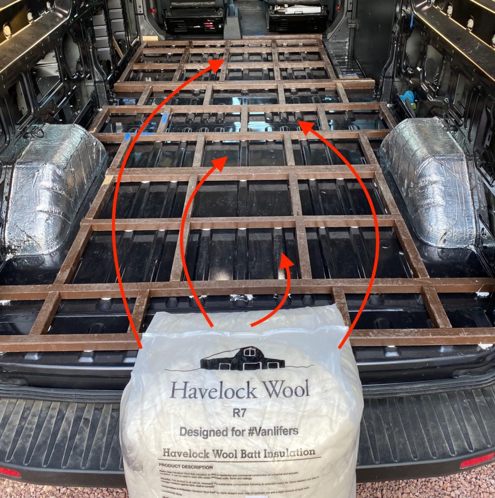
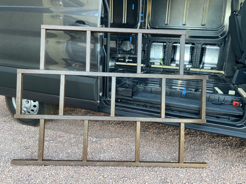
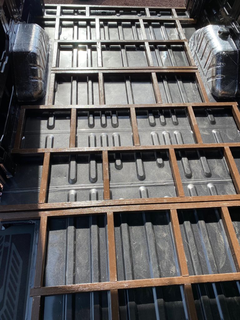
In Part 1 of this guide, I covered the steps to building a furring strip grid out of wood, which will rest on top of the corrugated metal floor, creating cavities that can be filled with Havelock Wool insulation. See the picture above and make sure to read Havelock Wool – Ultimate Van FLOOR Insulation Guide [Part 1] before continuing with this post.
Part 2 [this part] of the guide is a bit of a choose your own adventure… The order I completed these steps didn’t seem ideal, so I reordered them in hopes of simplifying the process for you. I encourage you to complete them in what ever order makes the most sense to you.
I sealed my furring strips before I completed Part 1 // Step 3: Building The Grid and I kind of regretted doing so. The product I used resulted in a sticky mess that made the subsequent steps more difficult. If you’re interested in sealing your floor with a moisture barrier, it seems better to wait until later in the process to do that. More on sealers in Step 5.
Another thing that didn’t work out so well was attaching the grid to the van floor before I cut out the plywood subfloor that would sit on top of it. I found myself tripping over the furring strips while working on other projects until I got around covering the grid with plywood and I even had to surgically remove a section of the strips that were in the way of where my air heater would eventually be located. In hindsight, I would have preferred to prep the plywood subfloor and finalize some layout decisions before gluing the strips down, that way the three grid sections could be temporarily removed from the van, or modified easily.
I’ll cover a few of the additional things you might want to consider at this stage of your build and before you proceed with any additional work on the floor, then we’ll pick back up where Part 1 left off in Step 4.
Tools & Materials You’ll Need
- Circular Saw
- 40 Tooth Circular Saw Blade
- Kreg Accu-Cut Circular Saw Track
- Jig Saw
- Jig Saw Blades
- 1/4″ spacers (5 gallon paint stir sticks worked well)
- 6-8 x 6″ Spring Clamps
- 2 x 24″ Trigger Clamps
- 2 x 12″ Trigger Clamps
- 3 x 1/2″ Sheets of 4’x8′ Birch Plywood
- 2 x 3M 4200 Marine Adhesive
- Caulking Gun
- Tape Measure
- Scissors
- Blue Painters Tape
Steps
- In Part 1 of this guide:
- In this part of the guide:
- Step 7… continues in Part 3 (coming soon)
Additional Floor Considerations
As mentioned at the end of Part 1, it’s worth thinking ahead and taking the time now to come up with a plan for any appliances that require drilling through the van floor, or anything else that may otherwise impact how you complete your subfloor.
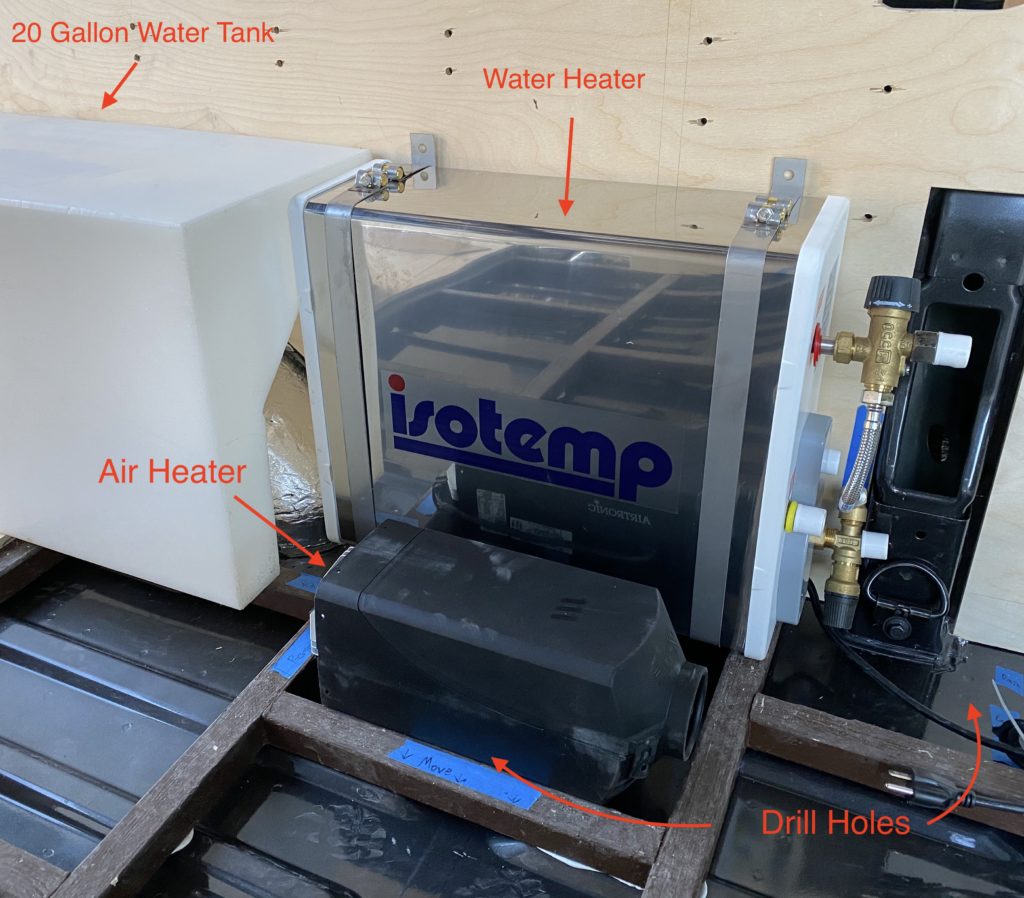
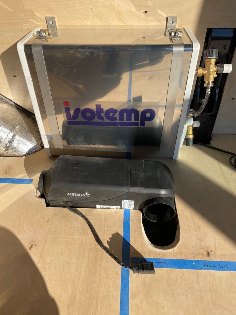
My build will include an IsoTemp Square water heater and Espar M2-B4L air heater, both of which require poking holes in the van floor. Once the insulation is in and the plywood subfloor is fastened to the furring strips, those types of jobs become much more challenging.
I will cover the full installation of both of these devices in future posts when I actually complete them. For now, my main concern is prepping the floor to make those projects easier later on.
In order to fit the Espar air heater in the location I wanted, I ended up having to remove one of the furring strip cross-members that I already glued to the van floor… which was not exactly an easy task. If I planned ahead, I would have moved that cross-member over when I attached it to the grid so the Espar would fit without requiring later modification of the furring strips. Building the grid with this type of thing in mind can definitely save some rework down the line!
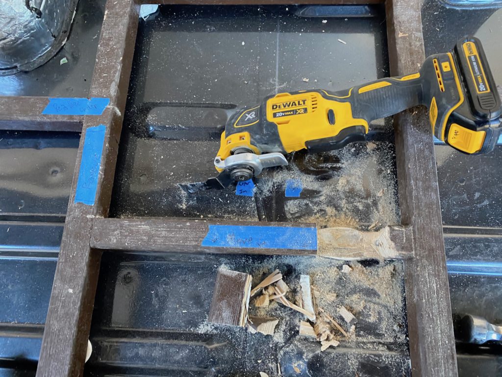
I hacked out the cross-member with an oscillating tool and then beat on it with a hammer and other tools to forcefully separate it from the van floor. As you’ll see in Step 6: Secure Grid To Van Floor, I used 3M 4200 adhesive which creates a “semi-permanent” bond. Based on the effort it took to remove the small section, I am confident the floor will be very stable and secure for a long time to come.
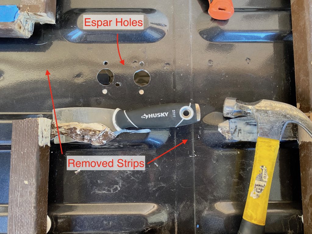
The Espar will sit flush with the metal van floor, and stick up above the subfloor, so an Espar shaped cutout will need to be made when the plywood is fitted in Step 4 coming up.
Your particular design requirements (including electrical and plumbing systems, appliances, etc) may require additional modifications to the floor. The earlier you can sort these out in your build the better!
Now that you’ve given all that some consideration, lets get back to building the floor!
Step 4: Scribe, Cut, Fit & Trim Plywood Subfloor
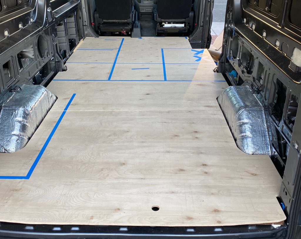
This post isn’t meant to be a comprehensive tutorial on scribing. There are various methods you can use and ample resources online to learn from. Simply put, its a method of transferring the profile of an object onto to a piece of wood that can be cut out to match its shape…. and in these vans, you can expect to be doing a lot of scribing! Those 4’x8′ sheets of plywood need to be cut to fit the contours of the van, where the floor and walls meet.
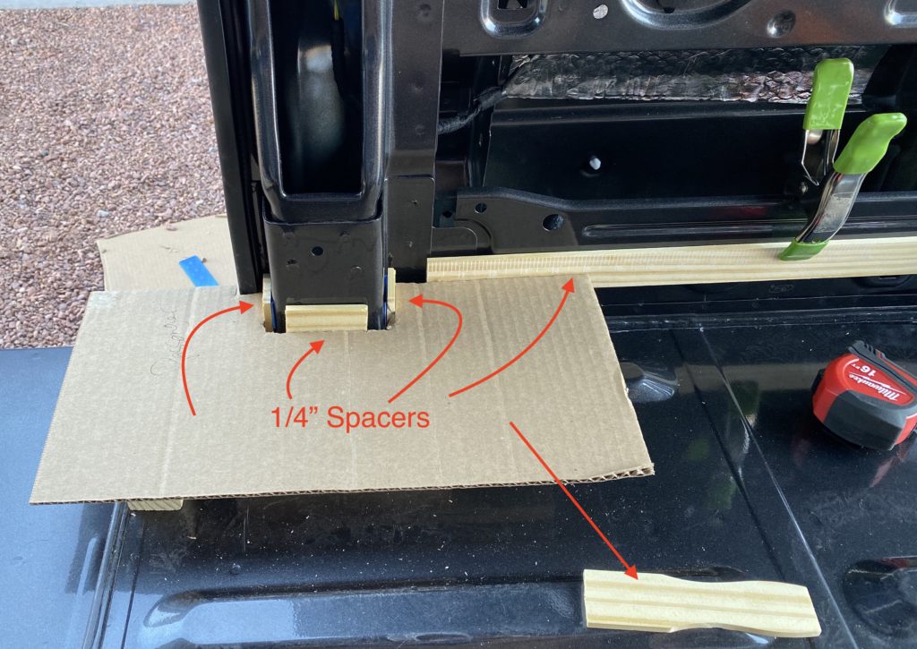
Wood rubbing on metal is a recipe for annoying squeaks and nobody wants those in their van! Leave some room between your subfloor and the walls to prevent them from making contact. In order factor that gap into the templates I was creating, I clamped and taped 5 gallon paint stir sticks to the walls, which gave me my desired 1/4″ spacing.
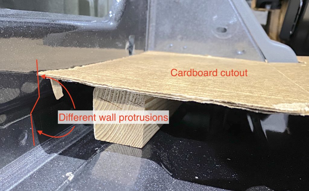
Its important to scribe your template onto the plywood while its sitting on TOP of your furring strips. The wall protrusions are different with the added height of the grid than if the subfloor was sitting directly on the van metal. Scribing at floor level will result in plywood sheets that do not fit on top of the furring strips.
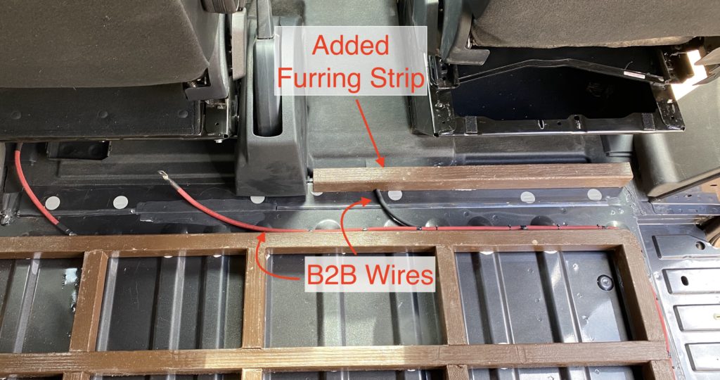
The corrugations on the floor that support the furring strips don’t extend as far forward as I wanted my floor to go. In Part 1 // Step 3, the cross-members built into the first row of the grid were only 7.5″ (instead of 14″) so that they line up with the beginning of the ridges on the floor. My subfloor stretches towards the front of the vehicle 6.5″ past the end of the furring strips. Worried about the lack of support at the transition from the wood subfloor into the front cab area, I ripped a 2×3 down to size and placed it behind the passenger seat, so that it supports the front edge of the subfloor. It ends up being approx 1.9″ high to be level with the furring strips that are sitting on top of the corrugations – measure the appropriate height for your floor.
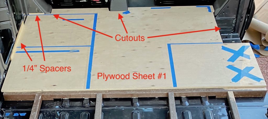
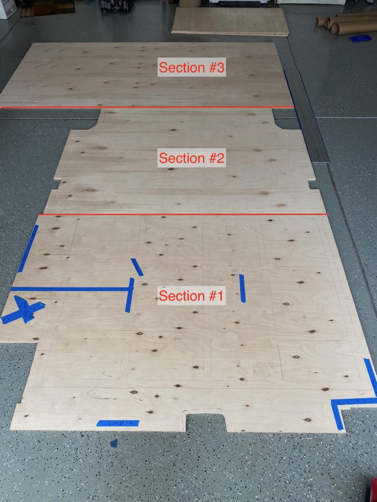
Subfloor Section #1
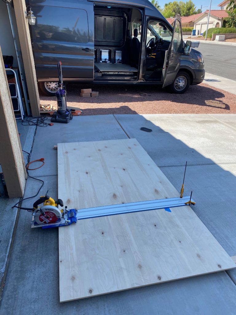
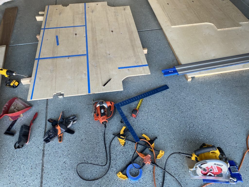
I started to prep the first subfloor section (behind driver and passenger seats) by ripping a 4’x8′ sheet of plywood into a 4-foot by 68-inch sheet, the widest this section will be in any spot. A circular saw with a finish blade and a circular saw track are must have items for this part of the build! Although Kreg claims this track wont slide around, I used small trigger clamps to secure the track to the plywood to ensure it didn’t wiggle at all while cutting.
Then I made a cardboard template of the driver and passenger side B-pillars and the parking brake, traced them onto the plywood and cut them out with a jigsaw. After a bit of test fitting and trimming, the sheet slid right into place. Then it was easy to trace along the underside of the plywood that was hanging over the step, using the edge of the step as a guide, and then cut it out. I decided to sacrifice about half the width of the step, leaving a section of the plywood hanging over the step where my fridge will eventually go.
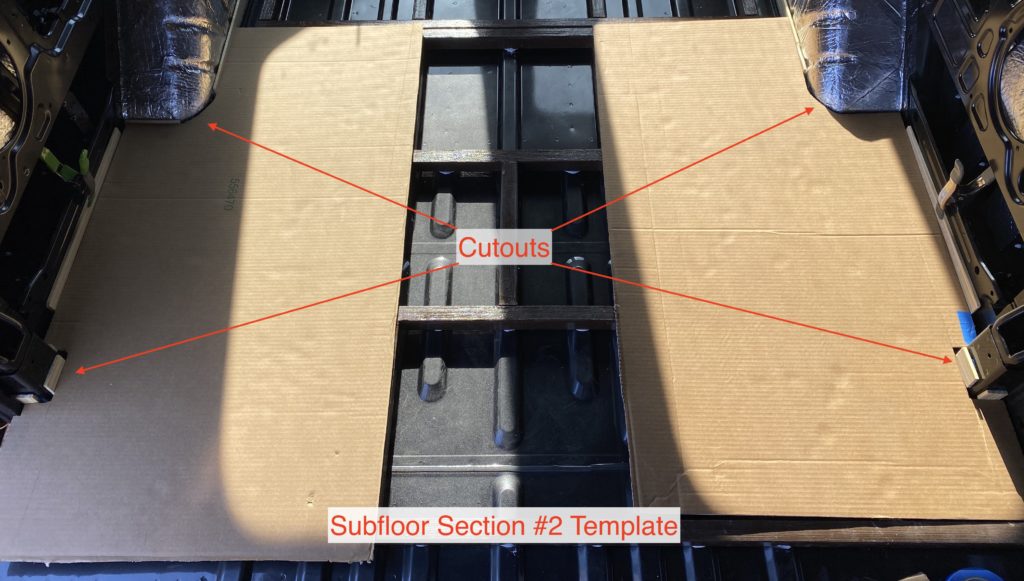
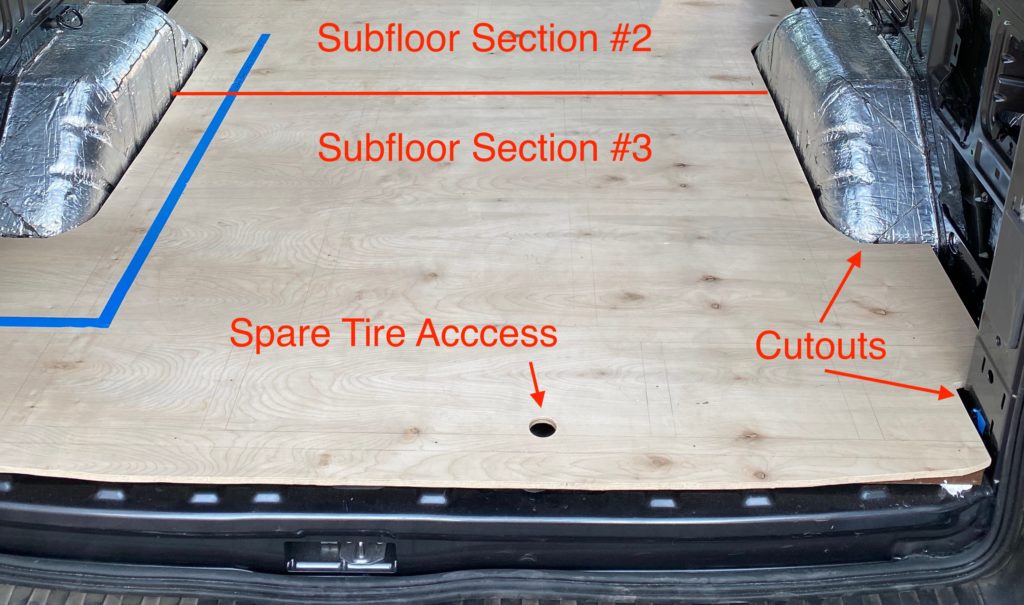
Subfloor Section #2
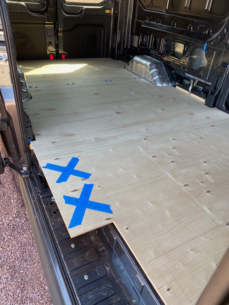
The second section of subfloor is quite a bit more involved, having to work around the C-pillars and wheel wells means lots and lots of scribing and cutting. Hopefully you found some tricks to making this process easier when you were completing the first section.
Once I had all of the individual cutout templates for this section made, I traced them onto giant sheets of cardboard to get the spacing of all of them correct before plunging a saw blade into a sheet of plywood. Measure twice, cut once… yeah?
Once I was happy with the giant cardboard template, I transferred it to a sheet of plywood. I triple and quadruple checked the measurements of the template as it was traced onto the board before cutting it out with a jig saw.
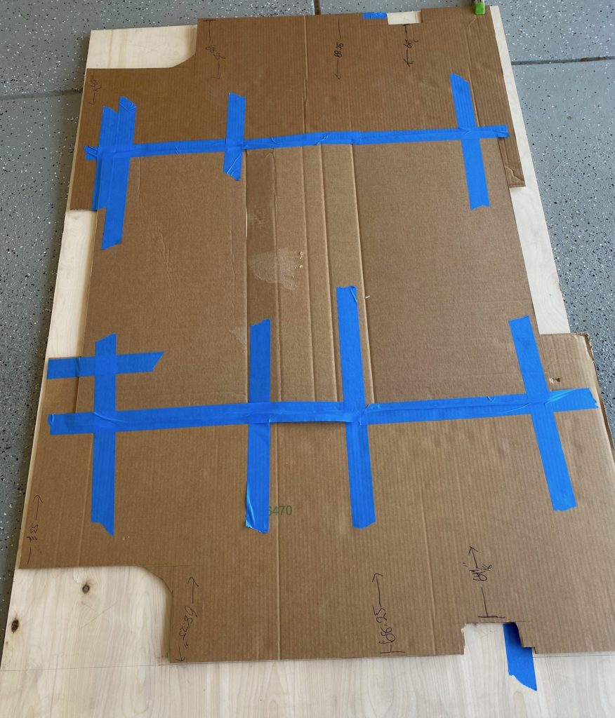
I’m happy to report it fit almost perfectly the first time with only a little bit of additional trimming necessary. On a side note, it is somewhat difficult moving these bulky and heavy sheets around. I used furniture sliders under one corner of the sheets to glide them back and forth from my garage working space to the van, which was effective, but if you have the option, get someone to help you move them in and out of the van.
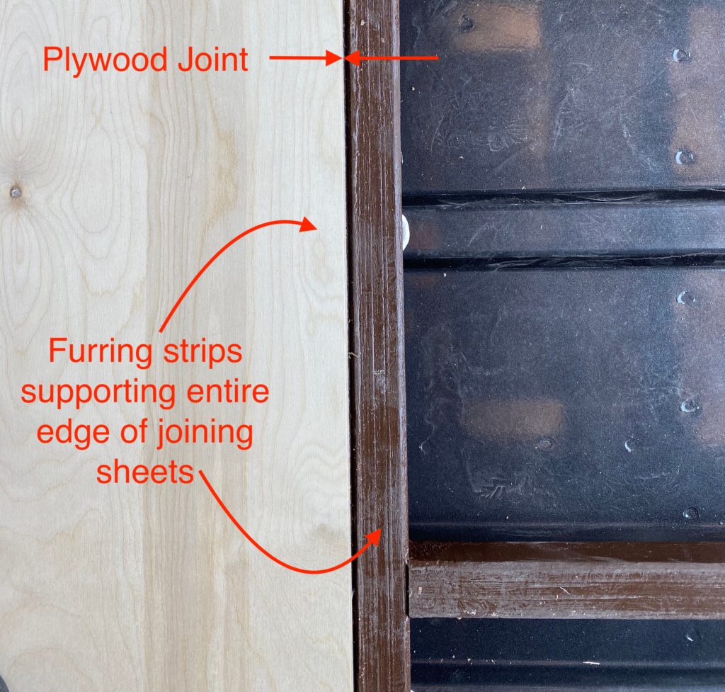
Now that there are two sections that will be joined together, lets take another look at how the floor is designed to maximize the stability of the subfloor at the seams. With two parallel furring strips where the joints are, the entire edge of both sheets is fully supported, preventing sagging or uneven floors. As you are scribing, cutting and fitting your plywood sheets, make sure the edges where they will join together are lined up with the double furring strip supports.
Subfloor Section #3
The final section of subfloor sits at the back of the van. The other half of the wheel wells and the D-pillars have to be scribed and then cut out of this sheet. By now, you should know exactly what needs to be done for those… get at it!
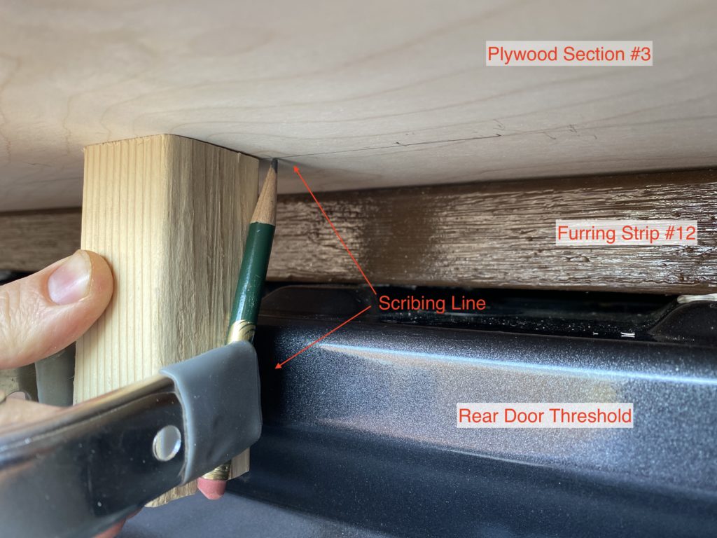
This last section wont stay 48″ wide like the first two, it needs to be trimmed to match the curve along the rear door. I rigged up a small pencil to a short 2×2 block with a 6″ spring clamp and slid it along the threshold to trace it onto the plywood . The section ended up being about 42″ after I cut off ~6″ with my jigsaw along the curved threshold.
The last thing to cut out of this sheet is a 1.5″ circle where the spare tire access hole is located using a hole saw bit. Hopefully you never get a flat, but if you do, you need to be able to access this area to lower the spare tire.
Rejoice, you have a subfloor! Well, almost. It may not be quite complete. Think back to the Additional Considerations above, was there anything else you came up with that will affect your floor?
Additional Considerations
For my build, I need to cut out a spot for my Espar air heater so that it can sit flush with the floor (and safely vent the exhaust out of the van). I measured out its approximate size and location onto the subfloor and used a jigsaw extract that area out.
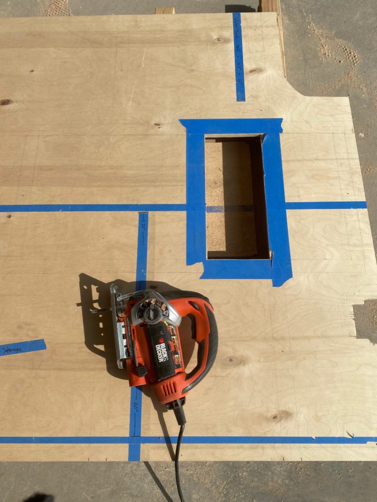
At this point, the Espar sat part way into the hole, making it slightly easier to scribe the exact contours of the intake and outlet ports so they fit nicely once its cutout. The hot air duct connects to the heater below the subfloor, so I cut out a small section of the subfloor to allow the tube to smoothly elevate up to the floor level (after the 90 degree hood).
I’ll be making a few other tweaks to the subfloor that are specific to my build. Make any others your build calls for, and then lets switch back to finishing up work on the furring strips.
Remove the plywood sections from your van and stack them somewhere, out of the way, where they’ll be safe. If sealing the furring strips is something you are interested in, continue to Step 5. Otherwise, when you’re ready to glue down the furring strips, jump to Step 6.
Step 5: Seal Furring Strips
While researching van builds and flooring, I came across several posts that recommended sealing the subfloor against moisture. This seemed logical, why take the risk that a water leak or condensation could get into the wood and cause mold or other problems down the line. Another thing that kept coming up was sealing the plywood to prevent off-gassing of potentially toxic chemicals used in the adhesives. Having clean and safe air to breathe living in a tiny space like a van is highly desirable, right?. AFMSafecoat came highly recommended as a brand of ecofriendly, safer, more natural paint products, so I reached out to for a product recommendation.
Dynoseal was the product they suggested for my van floor application. It’s a low-odor, all-weather, waterproof, vapor-proof coating and sealer that is highly resistant to flame spread and temperature change, and when cured is also highly resistant to gasoline, oil, grease, fungi, acids and alkalines plus it has sound dampening properties. Sounds good for a van, right!? It’s commonly used in roofing applications and is popular for sealing raised garden beds. It uses no solvents, formaldehyde, mildewcides or fungicides, making it safer than many alternatives. It was definitely more expensive than other sealer options, but I had high hopes for it, so I decided to give it a try…
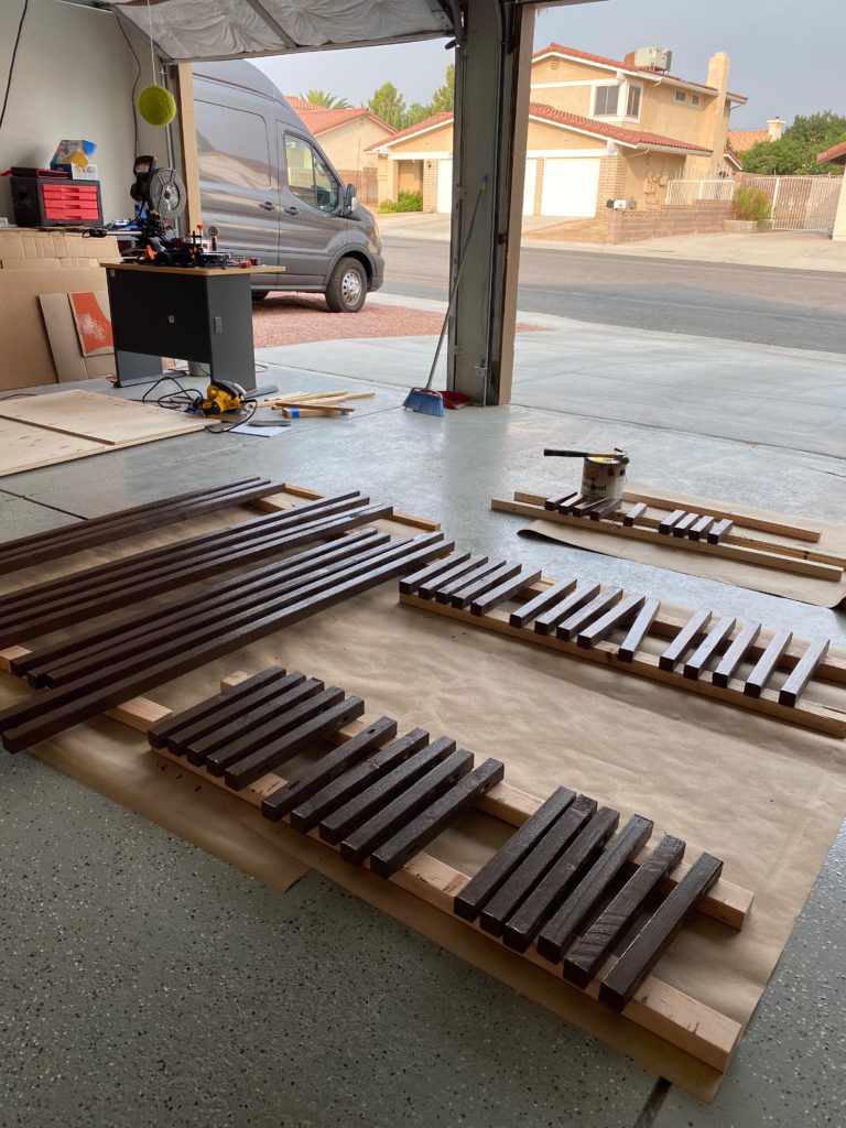
This sealer goes on quite thick, and remains tacky even after “curing” which quickly became a problem. The sealed strips became extremely sticky and would bond to anything they came in contact with, often some of the sealer would adhere to other objects and separate from the strips when pulled apart. They also stuck to the metal van floor when I was trying to position and build the grid which made that step significantly more difficult than it needed to be. I secured the sealed strips to the floor before I cutout my subfloor (Step #4) which meant the plywood was sticking to the strips while I was trying to fit them. Several projects were slowed down as a result of sealing the strips as early as I did and with the product I used. I’d definitely go about it differently next time.
I like the Dynoseal product for what it offers in terms of a sealer, but I can’t recommend sealing your floor with it like I did. I may have been more enthusiastic about the product if I sealed the three grid segments just before securing them to the van floor and if I covered them with plywood right away. There may be better products out there for this type of application. If you come up with any, please drop a note in the comments below about what you used and how it turned out for you.
*Update* See Part 3 of this series. I ended up sealing the top side of my subfloor with AFM Safecoat Safe Seal which I would recommend instead of DynoSeal for the furring strips if you are going to seal them.
Step 6: Secure Grid To Van Floor
I definitely did not want to drill a bunch of holes through the van to attach the floor using bolts. After a bunch of research and deliberation, I opted to use 3M 4200 Marine Adhesive to glue the furring strips to the stock floor. 3M 5200 is a more permanent option and would work well also. I used two full 10oz tubes of 4200 and felt the coverage was more than sufficient. Don’t forget to pick up a caulking gun to apply the adhesive.
Follow the instructions of your chosen adhesive to clean and prepare the van floor. Usually this will involve something like rubbing alcohol or acetone.
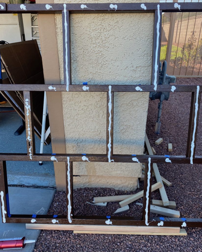
Once the surface prep was done, I squirted a bead of the 3M 4200 along the cross-members that sit on top of the ridges that run front to back. I also used dabs of adhesive where the strips that run the width of the van contact the top of the ridges. There’s no reason to waste adhesive where the strips span the valleys and don’t make contact with the body of the vehicle.
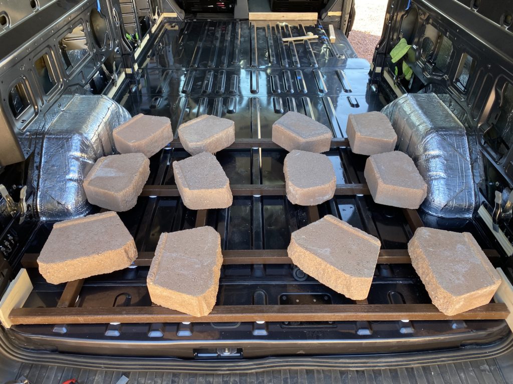
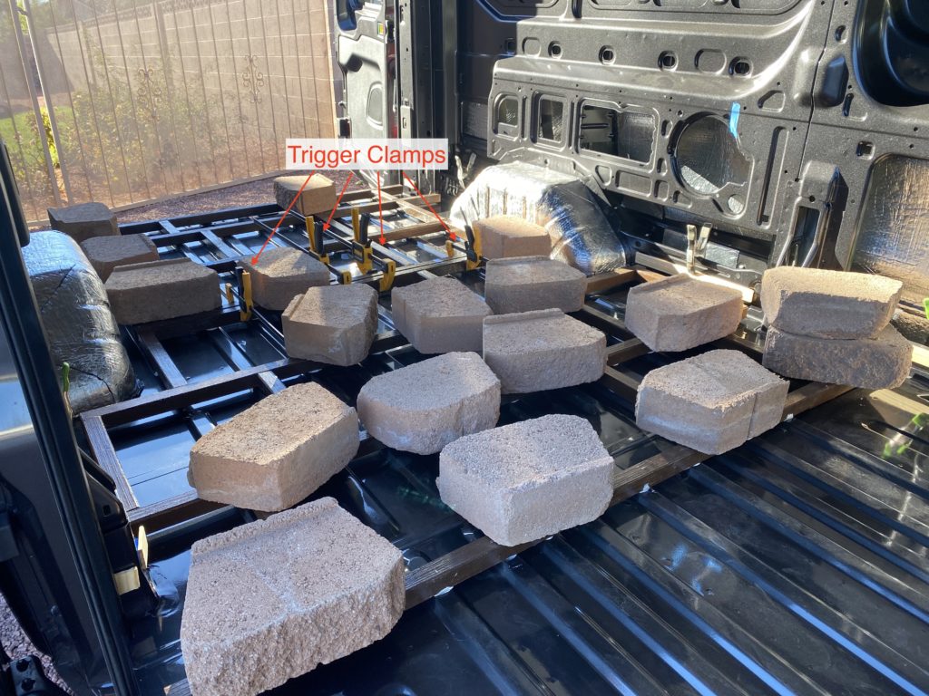
I attached the third grid segment (at the rear door) first and weighed it down, while the adhesive cured, with some bricks that I temporarily sourced from my yard landscaping. These created quite a mess of dust and little pebbles of stone that broke off which had to be vacuumed up once the floor was set. Sufficiently heavy items that don’t leave behind dirty messes would be preferred here.
A word of caution… My van was angled ever so slightly forward, and I noticed that with the weights on the strips, they were very slowly sliding towards the front of the van. I ended up using 24″ trigger clamps to hold the last strip (#12) to the rear door sill to prevent further slippage.
I allowed that rear grid segment to cure over night and then proceeded to the middle segment in the morning.
Trigger clamps once again come in handy to hold the grid segments together while gluing everything in place. Clamping strips #8 & #9 will help secure grid segment #2 to #3, and clamping strips #4 & #5 will help secure grid segment #1 to #2 (strip diagram). You can add a bead of adhesive to the joining faces of the grids before you clamp them if you’d like.
When you clamp the grid segments together, it’s critical that the top side of the two strips are level so the two sheets of plywood that meet at these joints lie flush with each other.
I let the middle grid segment cure before moving on to attaching the forward segment, mainly because I was limited in the number of bricks I could use to weigh the grids down. You could do it at the same time if you have enough trigger clamps and weights to secure everything in place.
Congrats! Your floor grid is complete. Continue to Part 3 for a step-by-step guide to:
- Installing Noico Sound Dampener
- Installing Havelock Wool
- Cutting Flooring Material
- Securing Subfloor to Furring Strips
- Installing Step
- Installing Flooring
- Installing Stair Nosing
- …and more!
Don’t forget to follow us on Instagram: @MauiTheVan
Enjoying your very detailed installs. I hope you have taken lots of similarly great photos and can cover your detailed install of the air and water heaters. Looking for good folks to follow when I build mine. Cheers
Thanks! I haven’t gotten to tackle those projects yet, but I definitely will document the installs and share them here. Keep an eye out on @MauiTheVan on instagram for new post announcements!